

PRINCIPLES OF PRESENTING DRAWINGS IN TECHNICAL DRAWINGS
Technical drawings are an indispensable part of the design and construction field, providing detailed information about the shape, size and structure of a product or construction. The presentation of drawings in technical drawings must comply with certain principles to ensure clarity, accuracy and ease of understanding. This article will present the basic principles in the presentation of drawings in technical drawings.
1. Types of strokes
Only the stroke types listed in the table below may be used.
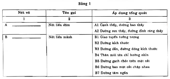
(1) – This type of line is used when drawing by machine
(2) – Only use one of the two types on the same drawing
When it is necessary to change the width of the line in some special industrial fields or if these lines have applications other than those listed in the third column of the table, an explanation must be provided on the drawing.
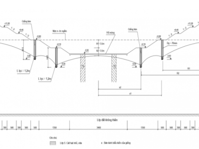
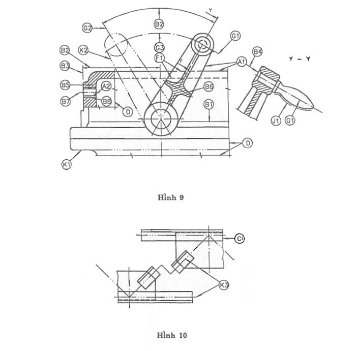
The lines specified in table 1 are illustrated in figures 9 and 10.
1.1. Solid line (Main line)
- Description: Solid line is a basic line, often used to show the outlines of shapes and main details. This line has a moderate thickness, is easy to recognize and is clear.
- Function: Solid lines help clearly define important components in the drawing, such as the edges of columns, walls, or other parts of the product. Solid lines are also often used to draw planes and borders of necessary areas.
- Characteristics: Solid lines should be 0.5mm to 1.0mm thick, depending on the standard regulations and the size of the drawing.
1.2. Dashed lines
- Description: Dashed lines are used to show hidden lines, invisible parts or secondary details. They are short dashes, usually spaced at a certain distance.
- Function: Dashed lines help provide information about the internal parts of an object without confusing the viewer. For example, in a column drawing, dashed lines can be used to indicate internal steel bars that are not visible from the outside.
- Characteristics: The distance between dashed lines is usually 1-2mm and the thickness of the line should be smaller than solid lines, usually from 0.25mm to 0.5mm.
1.3. Dotted lines (Flash lines)
- Description: Dotted lines or flash lines are lines made up of short, small, evenly spaced dots. This line is often used to show intersecting lines or unclear boundaries.
- Function: Dotted lines help emphasize intersecting areas or parts that need attention in the drawing. It can be used to indicate the location of cutting lines or sections in detailed drawings.
- Characteristics: The thickness of a dotted line is usually similar to a dashed line, from 0.25mm to 0.5mm, but the distance between dotted segments can be smaller, about 0.5mm to 1mm.
1.4. Cross hatch
- Description: Cross hatches are often used to show cutting details or cross sections of an object. This line can be simple or complex, depending on the requirements of the drawing.
- Function: Cross hatches help distinguish cross sections, allowing the viewer to understand the internal structure of the object, such as the location of parts, joints, or technical details.
- Characteristics: The thickness of the cross-hatched line can be similar to the main line, but can be slightly thinner, from 0.5mm to 0.75mm.
2. Width of strokes
It is allowed to use two line widths on a drawing. The ratio between the width of a thick line and a thin line must not be less than 2:1
The line widths must be selected to suit the size and type of the drawing and based on the following size ranges: 0.18; 0.25; 0.35; 0.5; 0.7; 1; 1.4 and 2mm.
The width of the same line in a drawing must be guaranteed to not change on different images of the drawing detail in the same ratio.
Note: The use of a width of 1.18mm is not recommended due to the difficulties of printing media.
3. Drawing rules
The minimum distance between two parallel lines, including the cross-section edge line, shall not be less than twice the width of the thickest line. This distance shall not be less than 0.7mm.
When two or more different types of strokes overlap, the following order of priority should be followed (see Figure 11):
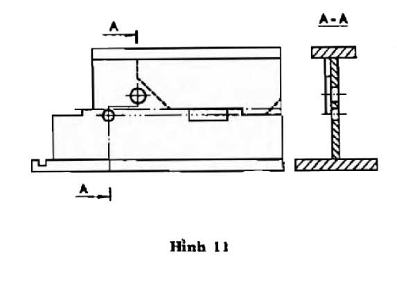
- Visible contours, visible edges (solid bold lines, type A).
- Hidden contours, hidden edges (dashed lines, type E or F).
- Cutting planes (thin dashed lines, bold at both ends and at changes of cutting planes, type H).
- Center lines and axes of symmetry (thin dashed lines, type G).
- Center lines (thin double-dotted lines, type K).
- Dimensioning lines (solid thin lines, type B).
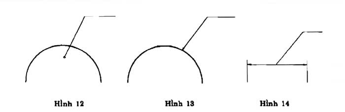
Leader lines relating to a certain element (dimension, object, contour, etc.) must be drawn offset from the other lines of the drawing to avoid confusion and must end:
- With a dot if the leader line ends inside the object's contour (see figure 12);
- With an arrow if the leader line ends on the object's contour (see figure 13);
- With no dot or arrowhead if the leader line ends on the dimension line (see figure 14).
4. Principles of drawing expression
4.1. Line thickness
- Principle: Each type of line should have its own thickness, making it easy for viewers to distinguish. Solid lines should be thicker than dashed and dotted lines. This creates a clear hierarchy for the information on the drawing.
- Note: If the drawing has many details, different thicknesses can be used to enhance the distinction. However, avoid making the drawing too complicated.
4.2. Spacing between lines
- Principle: The spacing between dashed and dotted lines should be even, ensuring consistency throughout the drawing. This not only creates harmony but also makes it easy for viewers to recognize the lines.
- Note: Reasonable spacing should be used to avoid making the drawing confusing. The spacing should also be adjusted according to the size of the object being shown.
4.3. Consistency in the use of line types
- Principle: In a drawing, it is necessary to maintain consistency in the use of line types. Each line type should be used for a specific purpose and line types should not be mixed.
- Note: If a line is used to indicate a specific aspect, it should not be used for another aspect in the same drawing.
4.4. Line Orientation
- Principle: Lines should be oriented appropriately to reflect the correct shape and structure of the object. Correct orientation helps the viewer to follow and understand the drawing easily.
- Note: In case of complex details, careful consideration should be given to the way of presentation to avoid confusion. Arrows or symbols should be used to guide the viewer to different parts of the drawing.
The principle of line representation in technical drawings plays an important role in conveying information clearly and accurately. Following these principles will not only make your drawings easier to understand, but will also improve the quality of your design and construction work. By paying attention to every little detail in your drawing, you will create professional technical drawings that meet the needs of your users.
5. Introducing a reputable design & construction consulting service provider
The importance of construction units is undeniable, their reputation will ensure the quality and aesthetics of your project. Currently, there are many units providing design and construction services to meet the increasing construction needs in our country. Therefore, finding a reputable unit is not easy and requires you to spend time researching. In the selection process, you need to research carefully and ensure that the accompanying unit must have high expertise, many years of experience, have a clearly signed contract, transparent costs, ... To help customers save time searching, Hung Nghiep Phu Construction Investment Co., Ltd. is confident that it will be the best choice for you.
Hung Nghiep Phu Construction Investment Co., Ltd. with the mission of providing the best solutions and services, building a prosperous community with customers, Hung Nghiep Phu is gradually affirming its brand through sincere cooperation, with a leadership team with ethical capacity, creativity, high expertise and strategic vision. Hung Nghiep Phu owns a team of skilled, highly qualified employees who will bring customers the best quality technology.
Hung Nghiep Phu Construction Investment Co., Ltd. - specializes in constructing civil and industrial works. We look forward to accompanying customers in construction projects as well as continuous procedures such as planning diagrams, applying for construction permits, completing procedures, applying for fire prevention and fighting certificates, ... If you have any questions or are in need of design, completing procedures, please contact us immediately for free consultation!
>>> See more:
_____________________
CONTACT INFO:
![]() Facebook: Công ty TNHH Đầu tư Xây dựng Hưng Nghiệp Phú (興業富)
Facebook: Công ty TNHH Đầu tư Xây dựng Hưng Nghiệp Phú (興業富)
![]() Hotline: 1800.3368 (Miễn phí)
Hotline: 1800.3368 (Miễn phí)
![]() Website: xaydunghungnghiepphu.com
Website: xaydunghungnghiepphu.com
![]() Gmail: kinhdoanh01@xaydunghungnghiepphu.com
Gmail: kinhdoanh01@xaydunghungnghiepphu.com
![]() Address: No. 2034D, Group 22, Phuoc Thai Hamlet, Tan Khanh Ward, Ho Chi Minh City
Address: No. 2034D, Group 22, Phuoc Thai Hamlet, Tan Khanh Ward, Ho Chi Minh City
------
Source: Compiled from the Internet