

CALCULATION OF INTERNAL FORCES OF HORIZONTAL FRAME OF INDUSTRIAL BUILDING STRUCTURE
The cross frame is an important part of the industrial building structure, responsible for transmitting and distributing the load from the roof, walls and other elements to the foundation. Calculating the internal force in the cross frame helps ensure safety and efficiency in the design. This article will discuss the process and factors to consider when calculating the internal force in the cross frame. Follow Hung Nghiep Phu to learn more about how to calculate the cross frame of the industrial building structure!
1. Diagram of calculating horizontal frame of industrial building structure
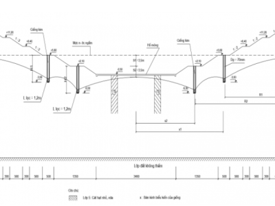
The purpose of calculating the frame is to determine the internal forces: moment, bending, longitudinal force, shear force in the frame sections. Calculating a rigid frame with hollow bars such as trusses and columns is quite complicated, so in practice, the actual calculation diagram of the frame is replaced by a simplified diagram, with the following assumptions:
- Replace the truss with a solid crossbar with equivalent stiffness placed at the lower flange elevation of the truss. The height of the frame is calculated from the bottom of the column (top surface of the foundation) to the bottom edge of the lower flange of the truss. The stiffness of the crossbar equivalent to the truss is calculated by the formula:
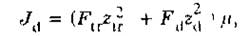
Where Ftr, Fd – cross-section of the upper and lower flanges of the truss; Ztr, Zd – distance from the centroids of the upper and lower flanges to the neutral axis of the truss at the mid-span cross-section; μ – coefficient taking into account the slope of the upper flange and the deformation of the beam. With a slope of i = 1/8, μ = 0.7; i = 1/10, μ = 0.8; i = 0, μ = 0.9.
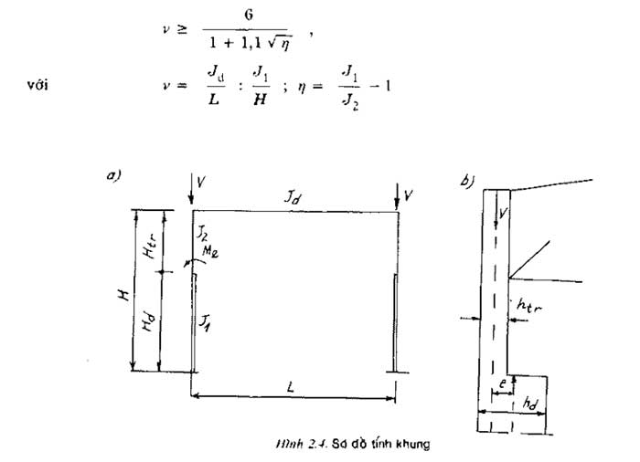
- For stepped columns, the axis of the lower column is made to coincide with the axis of the upper column, the design span is the distance between the two axes of the upper column. Then, with the vertical load transmitted from the upper column, the eccentric moment at the point of change of the column cross-section must be included:
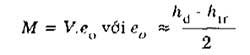
The column is viewed at the column base plate (at a depth below the ground surface H3 = 600 ÷ 1000mm as mentioned). The calculated height of the frame is taken from the column base plate to the bottom of the truss.
To calculate the structural frame of an industrial building, it is necessary to preliminarily give the stiffness J of the truss, of the column sections, or at least need to know the ratio of these stiffnesses. It is possible to preliminarily calculate according to the following formulas:
- Momen of inertia of the truss:
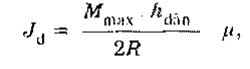
In which Mmax – momen bending moment in the crossbar, considered as a simple beam under the effect of the entire calculated vertical load; hdàn – height of the truss at the section with momen Mmax; R – calculated strength of steel.
- Momen of inertia of the lower column:
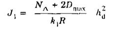
In which: NA - recalculated longitudinal force of column foot cross-section due to load acting on the roof; Dmax - pressure due to crane; hd - width of lower column; k1 - coefficient depending on column step: k1 = 2.5 ∼ 3 when column step is 6m; k1= 3.2 ∼ 3.8 when step is 12m.
- Momen of inertia of upper column:
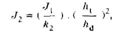
The coefficient k2 is taken as 1.2 – 1.8 when the truss is rigidly connected to the column, and as 1.8 – 2.3 when the connection is hinged.
The ratio between the stiffnesses Jd, J1, J2 can also be based on experience and assumed in advance as follows:
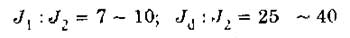
For multi-span industrial building structural frames, let J3 and J4 be the moments of inertia of the lower and upper parts of the middle column, then the ratio is approximately correct.

-
When the middle column step is twice that of the outer column, this ratio is 20 ∼ 60
If the actual stiffness ratio deviates from the assumed stiffness by no more than 30%, the calculated internal force is not much different and does not need to be recalculated.
When calculating frames with vertical loads applied directly to the truss, the truss deformations can be ignored (the truss is considered infinitely stiff Jd = ∞) if the formula is satisfied.
For frames with three or more spans, when calculating vertical loads or local horizontal loads applied to columns (such as restraints), the horizontal displacement of the column top can be ignored.
2. Calculating internal forces of horizontal frames of industrial building structures
The frame is solved in turn with each type of separate load considered above; using methods of structural mechanics; or pre-calculated formulas, numerical tables. Below, some commonly used calculation methods for frames with stepped columns are introduced.
To avoid confusion, the sign convention of the bending moment is as follows: positive momen when stretching the inner fibers of the beam and of the edge column; for the middle column, take the moment sign according to the edge column closest to it.
2.1. Calculating the frame with uniformly distributed load on the crossbeam
The displacement method can be used, the unknowns are the rotation angles at the nodes and the horizontal displacement of the column top; this displacement, as mentioned above, can be ignored in many cases.
For example, with a single-span frame due to symmetry, we have the rotation angle:
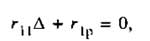
Canonical equation:
-
In which: r11 - total reaction momen at the upper nodes of the frame when rotating at angle φ = 1; r1p - total reaction momen at that node due to external load.
The convention is that the reaction momen and rotation angle are positive when the left column node rotates clockwise; the right column node rotates counterclockwise.
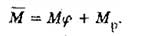
Let the two nodes above rotate at angle φ =1: Bending momen at the two ends of the crossbar; (considering the constant cross-section bar with two rotated clamped ends) is:
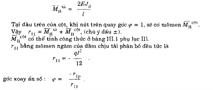
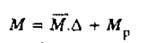
The final momen is equal to the momen in the basic system multiplied by the unit rotation angle times the angle φ just found; plus the momen in the basic system.
As mentioned above, when calculating with this type of load; the eccentric moment at the axis transition Me = V.e must be included. Because the frame has no horizontal displacement and the truss is considered infinitely stiff, the bending moment in the column is determined immediately according to the column diagram at the two ends of the clamp.
2.2. Calculating the frame with the crane moment
The frame is calculated simultaneously with the momen Mmax and Mmin placed at the two columns supporting the crane.
With the crossbar diagram being infinitely stiff; the unknown according to the displacement method is the horizontal displacement of the upper node:
- In which: r11 - reaction force in the additional link, due to the displacement of the upper node being equal to 1; r1p - reaction force in that link due to the load.
Resulting momen:
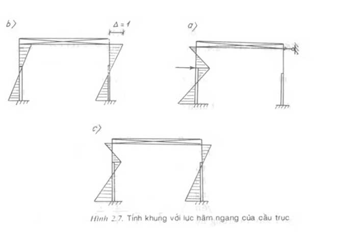
2.3. Calculating the frame with the horizontal braking force T
Force T is placed at the braking beam elevation of one of the two crane support columns. The force direction can be to the right, so the internal force of the frame always has a positive (+) or negative (-) sign; the (+) sign corresponds to one direction, the (-) sign corresponds to the other direction.
The calculation procedure is the same as when calculating with Mmax, Mmin. Moment diagram due to displacement Δ = 1.
3. Spatial working of the frame
When calculating the frame with the crane load (Mmax, Mmin and T), the spatial operation of the frame can be considered.
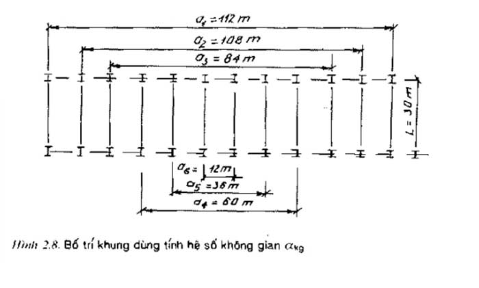
Thanks to the longitudinal bracing system at the bottom flange of the truss or thanks to the hard roof (a monolithic reinforced concrete roof; or assembled from large-sized panels), the local load placed on a frame will be transferred to the neighboring frames, thereby reducing the horizontal displacement. Consider the spatial operation of the frame by multiplying the space coefficient αkg into the displacement Δ calculated from the canonical equation.
In the case of a house with a hard roof, the coefficient αkg is calculated by the formula:
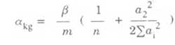
- In which, n - number of frames in a thermal block, connected by a hard roof; a1 - distance between two frames symmetrically oriented through the central axis of the thermal block (a1 is the largest distance; a2 is the distance between two frames close to the edge); m - coefficient considering the deformation of the hard roof; m = 0.9 for a single-span house with a vertical skylight; m = 0.95 for a two- and three-span house with a skylight or a single-span house without a skylight.
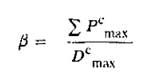
- β - calculated by the formula:
3.1 Calculating the frame with wind load
Follow the same procedure as for the running moment or braking force. Reuse the M diagram for the displacement Δ = 1 caused in the basic system and have r11.
Draw the moment diagram caused by q, q' in the basic system. In the left column, after calculating MB, RB, continue calculating the moment at other sections.
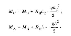
In the right column, the torque and reaction values are derived from the corresponding values in the left column by multiplying by the transfer coefficient q’/q.
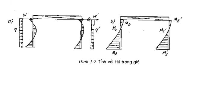
Reaction in additional link:
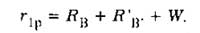
Displacement Δ = -r1p/ r11. Multiply Δ by M and add momen in the basic system to get the final moment diagram (Fig. 2.9b). The shear force is derived from the loads and reactions. When the wind blows from right to left, momen diagram will be the diagram of Fig. 2.9b inverted; in a mirror image.
3. Introducing a reputable design & construction consulting service provider
The importance of construction units is undeniable, their reputation will ensure the quality and aesthetics of your project. Currently, there are many units providing design and construction services to meet the increasing construction needs in our country. Therefore, finding a reputable unit is not easy and requires you to spend time researching. In the selection process, you need to research carefully and ensure that the accompanying unit must have high expertise, many years of experience, have a clearly signed contract, transparent costs, ... To help customers save time searching, Hung Nghiep Phu Construction Investment Co., Ltd. is confident that it will be the best choice for you.
 Hung Nghiep Phu Construction Investment Co., Ltd. with the mission of providing the best solutions and services, building a prosperous community with customers, Hung Nghiep Phu is gradually affirming its brand through sincere cooperation, with a leadership team with ethical capacity, creativity, high expertise and strategic vision. Hung Nghiep Phu owns a team of skilled, highly qualified employees who will bring customers the best quality technology.
Hung Nghiep Phu Construction Investment Co., Ltd. - specializes in constructing civil and industrial works. We look forward to accompanying customers in construction projects as well as continuous procedures such as planning diagrams, applying for construction permits, completing procedures, applying for fire prevention and fighting certificates, ... If you have any questions or are in need of design, completing procedures, please contact us immediately for free consultation!
>>> See more:
_____________________
CONTACT INFO:
![]() Facebook: Công ty TNHH Đầu tư Xây dựng Hưng Nghiệp Phú (興業富)
Facebook: Công ty TNHH Đầu tư Xây dựng Hưng Nghiệp Phú (興業富)
![]() Hotline: 1800.3368 (Miễn phí)
Hotline: 1800.3368 (Miễn phí)
![]() Website: xaydunghunnghiepphu.com
Website: xaydunghunnghiepphu.com
![]() Gmail: kinhdoanh01@xaydunghungnghiepphu.com
Gmail: kinhdoanh01@xaydunghungnghiepphu.com
![]() Address: No. 2034D, Group 22, Phuoc Thai Quarter, Tan Khanh Ward, Ho Chi Minh City
Address: No. 2034D, Group 22, Phuoc Thai Quarter, Tan Khanh Ward, Ho Chi Minh City
------
Source: Compiled from the Internet